
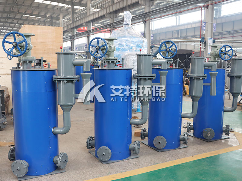
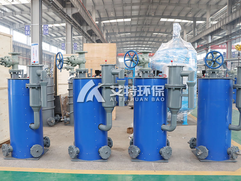
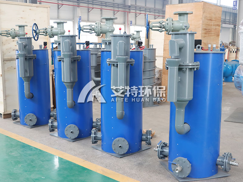
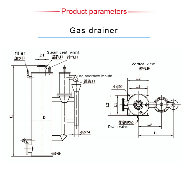
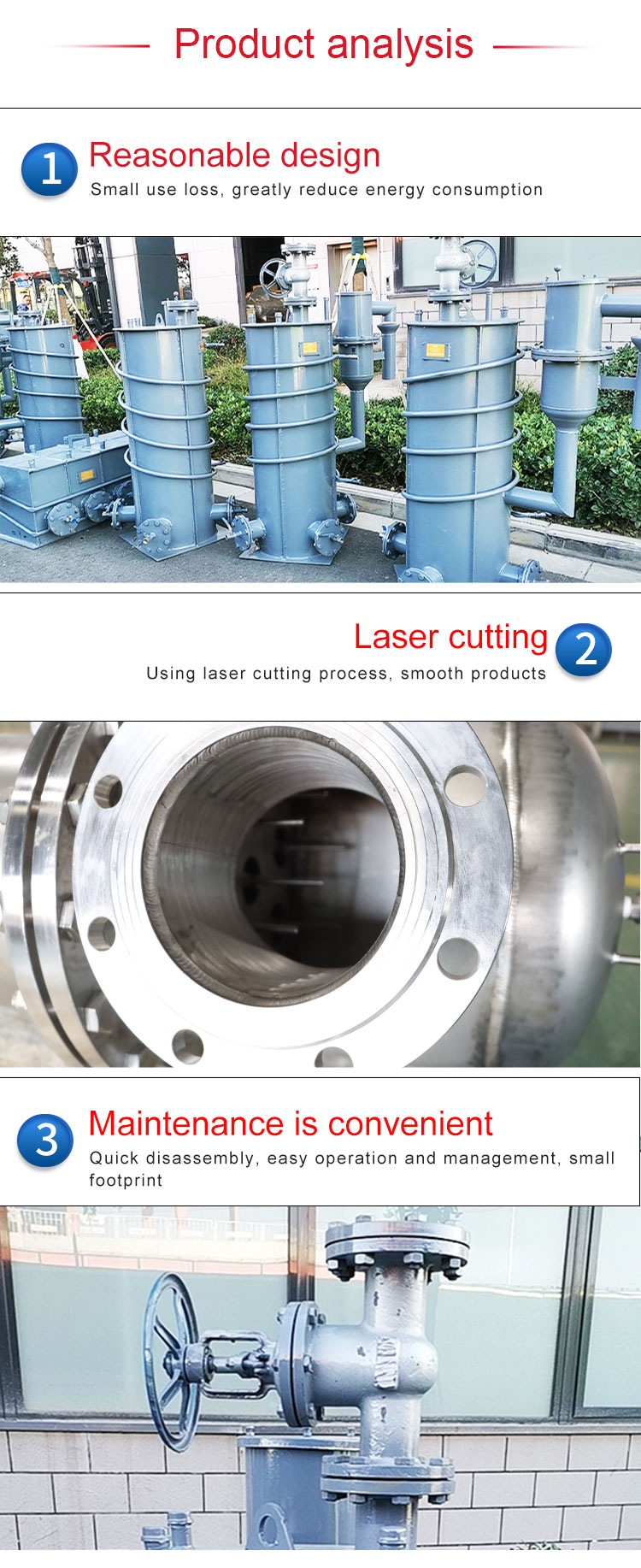
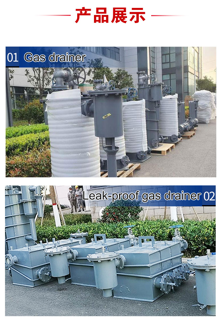
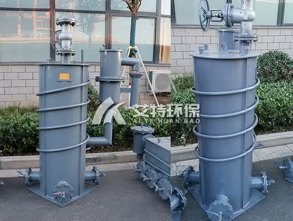
Electric tracing gas drainer is mainly composed of the body of the gas drainer and the leakage prevention device of the gas drainer.
Product Overview
The electric heat-tracing gas drainer is a specialized safety device engineered for condensate removal
in gas pipelines while maintaining reliable gas sealing to prevent leakage. Comprising two primary components—the
drainer body and an integrated leakage prevention device—this equipment serves critical functions in gas distribution
networks. Its main operating principles include: utilizing water seal height to effectively seal gas while discharging
condensate water; providing visual indication of sealing water level within the drainer; and, in the event of water seal
breakdown, automatically activating the leakage prevention mechanism to seal the gas and prevent hazardous gas escape.
By strictly controlling gas leakage, the electric heat-tracing gas drainer effectively prevents gas poisoning incidents and
fire hazards, making it an indispensable safety component in gas transmission and distribution systems.
In gas pipeline networks, condensate naturally accumulates due to temperature fluctuations and pressure changes.
If not properly drained, this condensate can cause pipeline corrosion, reduce flow efficiency, and even lead to blockages.
However, draining this water while maintaining gas pressure and preventing gas escape presents a significant engineering
challenge. The electric heat-tracing gas drainer addresses this challenge through a sophisticated water seal mechanism
that allows condensate discharge while maintaining a positive gas seal.
Operating Principle
The electric heat-tracing gas drainer operates on a well-established buoyancy-based sealing mechanism. The buoy is
constructed from a stainless steel hollow cylinder with a specific gravity lower than water, ensuring it floats on the
water surface. The lower portion of the buoy features a rubber cone that, when engaged with the outer shell's rubber
seating surface, forms a precision sealing interface.
During normal operating conditions, the leakage prevention device within the gas pipeline drainer is filled with water.
This water creates a separation barrier between the gas and the atmosphere, effectively sealing the gas within the pipeline.
As condensate accumulates, the water level within the drainer rises. When the water level exceeds the design height,
the excess water is automatically discharged through the leakage prevention device.
If gas pressure exceeds the water seal height capacity of the drainer, the water seal is temporarily "broken down."
At this critical moment, the leakage prevention device activates, and the drain outlet is tightly sealed by the buoy's rubber
cone against the shell seating surface. This instantaneous sealing action effectively blocks gas passage, preventing any leakage.
Once the water seal is re-established, normal operation resumes.
Heat-Tracing and Freeze Protection
The electric heat-tracing feature is particularly critical for installations in cold climates where condensate may freeze
and block the drainer. The system maintains the drainer and associated piping at temperatures above freezing, ensuring
reliable year-round operation. Optional configurations include:
· Electric Heat-Tracing: Uses self-regulating or constant-wattage heating cables wrapped around the drainer body and piping
· Steam Heat-Tracing: Utilizes steam tracing lines for facilities with available steam supply
· No Heat-Tracing: Suitable for installations where ambient temperatures remain above 0°C year-round
Selection Parameters
When specifying an electric heat-tracing gas drainer, the following parameters must be considered:
Installation Configuration
· Horizontal Installation: Requires 1.2 meters of clearance (excluding gate valve)
· Vertical Installation: Requires 1.5 meters of clearance
· Square Vertical Installation: Clearance can be reduced to less than 1 meter
Water Seal Height Determination
The water seal height is determined by the gas pipeline pressure. Typical water seal heights are 3 meters and 4 meters.
The calculation rule is:
· For gas pipe network pressures (typically less than 25 kPa): Add 500 mm of water column
· For critical applications: Add 800 mm of water column, then multiply by safety factor of 1.2
Example: For a 4-meter water seal with standard conditions: 4m + 500mm = 4.5m water seal height.
Connection Size Options
Standard inlet connections are available in:
· DN50, DN80, DN100, DN125, DN150, DN200
Material and Plate Thickness Specifications
Carbon Steel (Q235B) Construction:
· Cylinder wall thickness: ≥ 6 mm (minimum standard requirement)
· Pipe fittings: ≥ 5 mm
· Top and bottom plates: Typically 8 mm (or 10 mm for specific requirements)
Stainless Steel (304) Construction:
· Same thickness requirements apply
· Recommended for corrosive environments or high-purity applications
Application Fields
The electric heat-tracing gas drainer is widely deployed in:
· Natural Gas Transmission and Distribution: Mainline and distribution pipeline networks
· Coke Oven Gas Systems: Steel plant by-product gas handling
· Biogas and Landfill Gas Systems: Renewable energy gas collection
· Industrial Gas Pipelines: Chemical plant utility gas systems
· Coalbed Methane Extraction: Gas processing and transmission
Frequently Asked Questions
Q1: What is the purpose of the electric heat-tracing system?
The heat-tracing system prevents condensate from freezing within the drainer during cold weather. Frozen condensate can
block the drainer, prevent proper operation, and potentially cause the water seal to fail. Heat-tracing ensures reliable
year-round operation.
Q2: How do I determine the required water seal height for my application?
Water seal height is determined by the maximum gas pipeline pressure. Add 500 mm of water column to the pipeline
pressure (converted to mm H₂O). For critical applications, add 800 mm and apply a safety factor of 1.2. For most applications
with pressures under 25 kPa, a 3-meter or 4-meter water seal is standard.
Q3: What materials are used for the drainer construction?
Standard construction uses carbon steel Q235B with a minimum cylinder thickness of 6 mm. Stainless steel 304 is available
for applications requiring enhanced corrosion resistance or when handling corrosive gas streams.
Q4: How does the leakage prevention device work?
When the water seal is intact, the device allows condensate to discharge normally. If gas pressure exceeds the water seal
height and breaks through, the buoy rises with the water level, and the rubber cone seals against the seating surface,
preventing gas from escaping through the drain outlet.
Q5: Can the drainer operate without heat-tracing?
Yes, in regions where ambient temperatures remain above 0°C year-round, heat-tracing is not required. However,
for installations in colder climates, electric or steam heat-tracing is recommended to ensure reliable operation.
Q6: What is the recommended inspection and maintenance schedule?
Weekly visual inspection of water level sight glass and heat-tracing system functionality is recommended. Monthly
inspection of the buoy, rubber sealing cone, and seating surface for wear or damage. Annual comprehensive inspection
including pressure testing and corrosion assessment is advised.
Q7: What are the installation clearance requirements?
Horizontal installation requires 1.2 meters of clearance below the drainer (excluding gate valve). Vertical installation
requires 1.5 meters. The square vertical configuration allows installation with less than 1 meter of clearance.
Q8: Is the drainer suitable for high-pressure gas pipelines?
The standard drainer is designed for gas pipeline pressures typically below 25 kPa (approximately 2.5 meters water column).
For higher pressures, consult our engineering team for custom design with increased water seal height and reinforced
construction.
Q9: Can the drainer handle low-temperature gas streams?
Yes. The electric heat-tracing system is specifically designed to prevent freeze-up. For extremely low ambient temperatures,
additional insulation and higher wattage heat-tracing may be required.
Q10: How do I know if the water seal has been broken down?
The drainer is equipped with a sight glass or level indicator. If gas bubbles are observed escaping through the water,
or if the pressure downstream of the drainer fluctuates unexpectedly, it indicates potential water seal breakdown.
The leakage prevention device will automatically seal to prevent gas escape, but the water level should be restored promptly.
Q11: What is the expected service life of the rubber sealing cone?
With normal operation, the rubber cone typically lasts 2–5 years. Replacement should be performed when visible wear,
cracking, or hardening is observed during inspection.
Q12: Do you offer custom configurations for specific applications?
Yes. We offer custom water seal heights, larger connection sizes, special materials, and integrated control systems for
remote monitoring and automated operation. Please provide your specific requirements to our engineering team.
For technical support, custom configurations, or application-specific recommendations, please contact our engineering team.
We provide complete solutions including design, supply, installation supervision, and after-sales service.
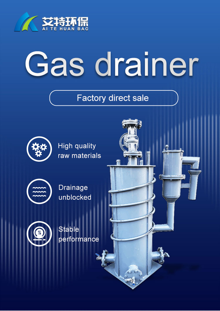
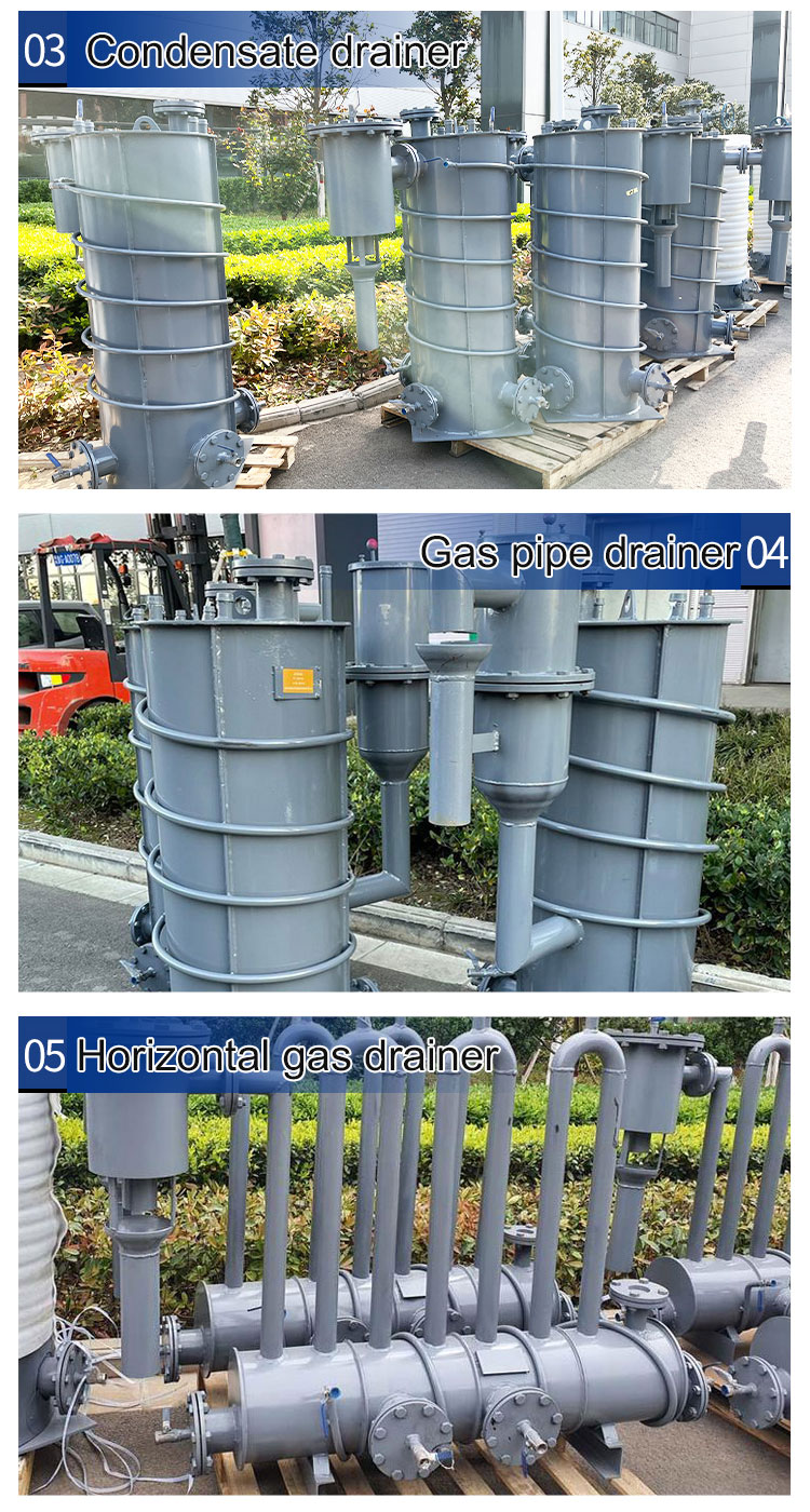
Electric heat tracing gas drainer
Similar ProductsVIEW MORE >
WhatsApp / Wechat: +8613273719759
Factory Address: Zhengshang Navigation Square, South Hanghai Road, Erqi District, Zhengzhou City, Henan Province P.R.China.


 Export01@aiteeps.com
 ++8613273719759
